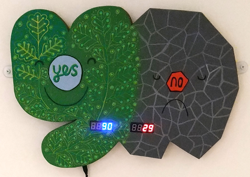
Step By Step PDF of how to build a “Yes/No” custom buttons display with a Raspberry Pi Pico, 2 x Custom Made Buttons & 2x7segment 4 digit LED backbacks
We have uploaded a PDF of the steps to build a “Yes/No” Custom Button + LED Digit displays on a raspberry Pi Pico , with step by step guide on how to make the custom wooden buttons, and the easy implementation of the adafruit_ht16k33 library for the LED Backpacks.
You can also download the zip file of the code here.
Phil is working away on the “Oop Tree” on the Pico, but is getting into “slow progress” with getting to grips with the implementation of how the tree will be affected by various inputs (water, food, light).
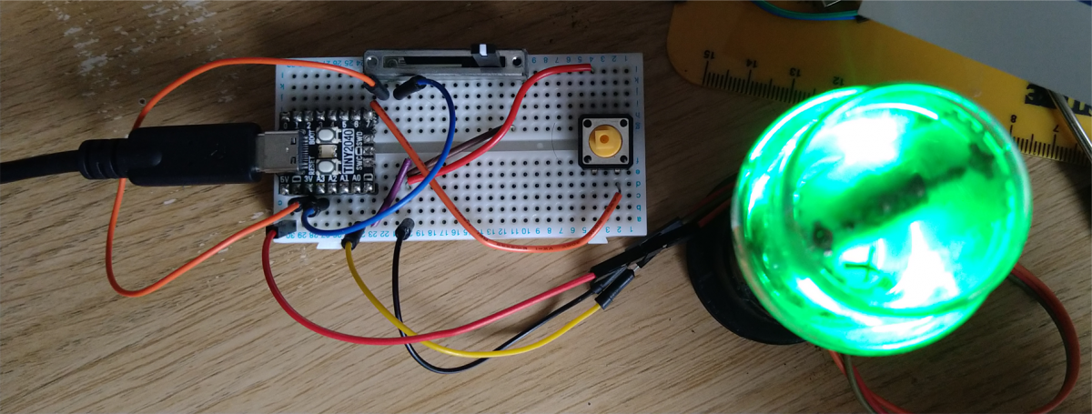
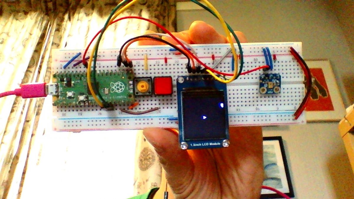
So as a “quick show n tell” – he’s put together a quick project using a #pimoroni #tiny2040 microcontroller, again, running the latest version of #circuitPython. Having found a box of old blown Valves (Beautiful objects!) Phil thought he would try to convert them into a useful light, using an RGB led, a button and a sliding potentiometer.
Phil did wire up a classic 4 legged RGB led & got it working, but had some very neat, single “NeoPixels” from Ada Fruit lying around, so soldered some pins onto one & used that, as instead of needing 3 separate pins to control the Red Green & Blue pins, you can do that all through one pin on the NeoPixel. There’s even a handy library to help ease the controls of changing the light colours / intensity.
First, Phil wired the push button into a digital pin (GP7) + Ground, then added a sliding potentiometer (you need 3 connections for this input, a constant 3v, a ground connection, then your “reading” (analogue) connection (A3)). Lastly, phil connected the 3 wires (5v, Gnd + A0) to the NeoPixel. Because you can “chain” NeoPixels, be sure to use the “in” side of the NeoPixel. Phil then drilled a hole into the base of the old Valve, he did this outside (well ventilated) and wore a mask, just in case there are any nasty old chemicals inside the housing or valve itself.
The full code for Phil’s RGB Led can be found here and a wee explanation below:
This project uses a single pushbutton to “cycle through” different states the NeoPixel uses. There is a Dictionary (Dict) that keeps information for LED levels (a “Base” RGB colour + “mix” (potential new levels to be added to the base colour). Each Dict Key is a string that should make the values obvious! The last setting is to make the slider decide what colour the RGB led should be…
Using a few functions Phil wrote for previous projects, you can now pass two tuples (r,g,b) and add them together to return the “mixed” (r,g,b) value – and apply it to the NeoPixel with the simple library method “pixels[0] = (r,g,b)” and “pixels.show()” (to update the NeoPixel).
The slider affects the possible “maximum mix” value by first converting its raw value (130 to 65000+) to 0 & what ever the current maximum value is for that “mix” (stored in the dictionary) this is done for each value (r, g, b). So when the slider is at “0” the maximum possible random number is between 0 & 0 (no new colour added to the base colour!) the higher the slider goes, the more randomness for each Red, Green, Blue “mix” value is possible… so the light starts to flicker within the range of the “base + mix” values…
The Slide setting uses a “wheel” method from Ada Fruit, and we “just” need to map the slide value (again from 130 to 65000+) to 0 & 255. When the slider is moved, it takes its position & passes an RGB value to the Neopixel to cycle from Green to Green over the spectrum. Nice.
Not much to show this week from Phil, he’s been getting deep into learning more about OOP in Python, and running into several problems that led him to more exploration, experimentation & fails (so, as we said, not much to show). He also sadly lost his 22 year old cat “Link” this week…
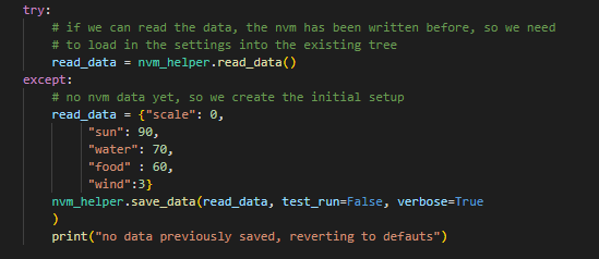
He did however, last week get into “NVM” (Non Volatile Memory) – A very elegant way of writing data to the Pico, so you can save info & recall it when the Pico Starts up again… We had tried using it for the Dinky OSC, but the older versions of CircuitPython didn’t support it, or at least were buggy with the ability to save without hanging the Pico (and forcing “Nuke ReFlashes!”).
Martin had read on the fantastic CircuitPython discord channel that the NVM issues had been addressed in the latest version. And so Phil re-opened his exploration of the use of NVM on a Pico… Phil did a quick search on discord & found :
Phil followed the link, downloaded the library from FoamyGuy and within minutes, had a fully working, easily updateable way of reading & writing info to NVM ! Like a dream you can save a dictionary via NVM_helper & all the byte conversions are sorted in that amazing script… So! Phil is back on track to keep track of the digital Tree , so we can implement the Real Time Clock & apply the effect of time to the tree depending on how often the tree is watered & fed & given sunlight! We will then hopefully see the fully working Tamagochi-esque digital tree…
For our new project we think at some point we are going to need to have an accurate measure of time that has passed and for this we will need a real time clock.
For our new project we think at some point we are going to need to have an accurate measure of time that has passed and for this we will need a real time clock.
The Pico doesn’t have it’s own clock, and for that matter non of the Raspberry Pi family do, a quick google search revealed a few different boards that could offer this facility.
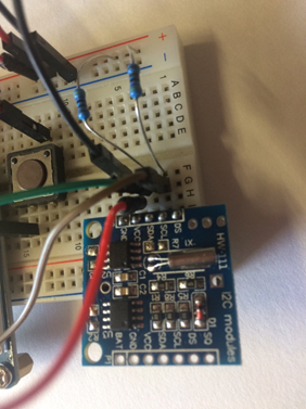
I decided to go with one that was based on a DS1307 and communicated via I2C. I ordered three of them from Amazon at a cost of £4.99. They arrived complete with installed batteries, with a claimed running time of a few years which would be more than enough for our project.
DS1307 Module
Another Google search was undertaken to find out how to connect them to a Raspberry Pi Pico. Most articles suggested that they were primarily a 5V device as they were originally designed for use with an Arduino and so would need to have two pull-up resistors moved from the board for use with the 3.3V system of the Pico. The resistors are R2 and R3 in the above image. The boards also needed to have headers installed.
Connections
Only four connections were needed: GND: Ground VCC: 3.3V SDA: GP0 SCL: GP1
Luckily CircuitPython has a library for use with the DS1307, complete with an example code listing.
I installed the required libraries and ran the example code. An error came up complaining about a lack of pull-up resistors.
Martin’s RTC Set up with Resistors…
I installed a couple of resistors, anything around 3.3k should be fine, between the SDA/SCL pins and VCC (3.3V) and ran the code again.
This time there were no errors. The code, see below, has a part where you can set the time by changing the ‘if False’ statement to ‘if True’. Once this has been done change it back to False. The RTC clock will continue to keep the time even after the Pico has been powered off.
Code listing
import time
import board
import adafruit_ds1307


# To create I2C bus on specific pins
import busio
i2c = busio.I2C(board.GP1, board.GP0)    # Pi Pico RP2040

rtc = adafruit_ds1307.DS1307(i2c)

# Lookup table for names of days (nicer printing).
days = ("Sunday", "Monday", "Tuesday", "Wednesday", "Thursday", "Friday", "Saturday")

if False:  # change to True if you want to set the time!
    #                     year, mon, date, hour, min, sec, wday, yday, isdst
    t = time.struct_time((2022, 5, 6, 15, 2, 15, 5, -1, -1))
    # you must set year, mon, date, hour, min, sec and weekday
    # yearday is not supported, isdst can be set but we don't do anything with it at this time
    print("Setting time to:", t)  # uncomment for debugging
    rtc.datetime = t
    print()
# pylint: enable-msg=using-constant-test

# Main loop:
while True:
    t = rtc.datetime
    # print(t)     # uncomment for debugging
    print(
        "The date is {} {}/{}/{}".format(
            days[int(t.tm_wday)], t.tm_mday, t.tm_mon, t.tm_year
        )
    )
    print("The time is {}:{:02}:{:02}".format(t.tm_hour, t.tm_min, t.tm_sec))
    time.sleep(1)  # wait a second
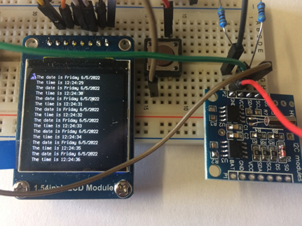
Readouts from the RTC
Realisation
After doing this I realised that because I was connected to pin 36 (3V3 out) that I hadn’t actually needed to remove the on board resistors and wouldn’t need the added pull-up resistors either.
I soldered headers to the remaining two boards to test that I was correct and indeed I was. So we now have three working realtime clocks, but one of them needs pull-up resistors.
Object Orientated Programming in CircuitPython to make Digital Trees
We think we’ve taken the Asteroids development as far as we can just now (looking at speeding up the FFT calculations)… but, in the mean time, Phil has started re-visiting an old passion… OOP Trees!
Object Orientated Programming in CircuitPython to make Digital Trees… Phil used to play with Macromedia Director 8 / 8.5 (!) and made some digital trees. Phil’s had an idea of re-visiting making OOP trees, but on the tiny Raspberry Pi Pico using CircuitPython…
Over 2 days, Phil’s successfully written a Tree Class, thinking of a tree as a series of “nodes” – He passed several key parameters to the Tree Class, an X,Y location, how many nodes the tree will have (“the Trunk”), how much those nodes can vary in direction from each other & how far they will be from each other. t = Tree() # Params cut out for ease here
Phil had a brainwave, to define all the lengths & angles “at the start” – and then “simply” multiply the values by a scale (from 0 to 1) – the “age” of the tree… so the entire tree is drawn but “scaled down” (to 0) at the start & in a loop, slowly increase the tree’s “age” by a tiny increment… giving the impression of growth! (it all worked smoothly! Not bad for a self taught N00B(!) – Phil’s sure there are probably a lot of pythonic conventions that need to be learned! ).
So, having a “working trunk” growing & stretching nicely, Phil wondered about adding branches… The thing is, they are nearly identical to a Trunk, just that the base of the 1st node isn’t “at a fixed point” (in the “ground”) – but a node on the Trunk (or even another Branch!). With a quick addition of “fNode” (“follow node”) – the Trunk having fNode = None & a branch having fNode = parentNode, he added in the code.py t.newBranch([2,3,3,4, 10]) The array passed, are positions of nodes in t (duplicates just add more branches to that node!). He even put in an error check to see if a node requested is in the range of the parent’s nodes! IT ALL WORKED! woohoo! The Branch grows just like the Trunk, but its base node follows the position of its parent node!
With the branches & trunk now growing nicely (and stopping growing when it reaches the scale of 1), Phil turned to add in leaves… a new Class “leaf” was added to the script & contains info of a colour of leaf, the radius of the leaf (using vectorIO.Circle objects) . Phil thought that the control of when / where & how many leaves appear should be decided by each node (on the trunk or branches). Passing several random numbers to determine how many, how big, how far away from the node they should be was passed in to the object. A few functions Phil’s made (“utility scripts”) like getting an X,Y position based on a known x,y position + length & angle (using Pythagoras) & adding a random range of R G B values to a “base R G B” colour to get variations of greens / browns (any colour!) – Phil rendered out leaves a hoy! But, things were slowing down again on the tiny Pico… So Phil decided to only render leaves when their parents reached specific criteria (age / length away from root) – and this gave a lovely effect of the leaves slowly blinking into existence, as the tree aged!
Phil was inspired & energised , getting into a “playful” development state…”I’ll try this!” he thought… boom! it works! And so, he added a few playful things, like a random “gust of wind” that jiggles the nodes occasionally, increasing & decreasing the scale quickly with the 2 buttons from week 1 … so many possibilities …
Anyway, if you want to have a play (& probably hone / improve the OOP!) download the scripts for the Pico set up here. Have fun!
We wanted to combine the knowledge gained previously from Phil’s Asteroids and Martin’s FFT code to make a game controlled by sound. Phil continued his work on the Asteroids and control of a small rocket capable of firing projectiles. Martin looked at isolating individual tones, these could then be used for the control of the rocket. Three tones were needed for, boost, rotate and fire. He chose an online tone generator https://www.szynalski.com/tone-generator/ to generate the three required tones.
"""FFT Tone detection
to work with ulab on Raspberry Pi Pico"""

from time import sleep
import audiobusio
import board

from ulab import numpy as np
from ulab.scipy.signal import spectrogram
import array

#---| User Configuration |---------------------------
SAMPLERATE = 16000
SAMPS = 256

fft_size = 256

# ============== make the PDM mic object =============== #

mic = audiobusio.PDMIn(board.GP27_A1, board.GP0,
                                sample_rate=SAMPLERATE, bit_depth=16, startup_delay=0.05, mono=True)

#use some extra sample to account for the mic startup
samples_bit = array.array('H', [0] * (fft_size+3))

# Main Loop
def main():
    max_all = 10
    while True:
        mic.record(samples_bit, len(samples_bit))
        samples = np.array(samples_bit[3:])
        spectrogram1 = spectrogram(samples)
        # spectrum() is always nonnegative, but add a tiny value
        # to change any zeros to nonzero numbers
        spectrogram1 = np.log(spectrogram1 + 1e-7)
        spectrogram1 = spectrogram1[1:(fft_size//2)-1]
        peak_idx = np.argmax(spectrogram1)
        peak_freq = peak_idx * 16000 / 256 / 2
        #print((peak_idx, peak_freq, spectrogram1[peak_idx]))

        if peak_freq > 1000 and peak_freq < 1150:
            print("Fire")
        elif peak_freq > 500 and peak_freq < 550:
            print("Rotate")
        elif peak_freq > 225 and peak_freq < 275:
            print("boost")
        else:
            print(peak_freq)
        sleep(0.1)

main()
The code worked reasonably well so the next task was to incorporate it into Phil’s asteroid code.
This proved quite challenging as once the two were combined together. The frequency returned by the microphone was always 0.0.
Various methods were tried, adding the Mic as object, calling it as a function and directly adding it to the main code.py. Adding it to directly to code.py was the final stage but still wasn’t providing the desired results.
Next we resorted to commenting out elements of code, the final conclusion was that some of the print statements were causing timing errors that caused the spectrogram to return values of 0.0. We aren’t quite sure why but once these were reduced to a minimum the code started working.
The final code with libraries is available as a zip file here.
It’s quite slow – the FFT calculations might be pushing the Pico to the edge of its computing power! Phil is exploring how to hone the OOP too, to see if he can eek out a few more milliseconds
With the use of the FFT code to recognise sounds / frequencies, we had an idea that a game could be controlled with specific sounds
With the use of the FFT code to recognise sounds / frequencies, we had an idea that a game could be controlled with specific sounds… Phil started to look at OOP again (Object Orientate Programming) & wanted to create a game of “Asteroids” but instead of pressing a button to “shoot” , making a laser “pew pew” sound would activate the shooting … Ambitious? has it been done before?
Phil loves a bit of OOP, and recently bought the fantastic book by Dusty Phillips and with the previous lessons in creating vectorIO polygons, he started out making a large polygon with randomly spread out “nodes” (thinking about large “initial” asteroids and how they would break down & split into smaller objects, with their own properties of speed, direction (vectors), edges etc).Phil’s 1st attempt at creating Asteroids
There are a few bugs, mostly from edge detection / re-draw – but it’s looking promising!
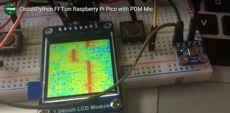
Martin has been following the #AdaFruit example of FFT
Martin has been following the #AdaFruit example of FFT ( fast Fourier transform) to convert the microphone input into a visual representation (spectrum) with great results! The code for this can be downloaded here
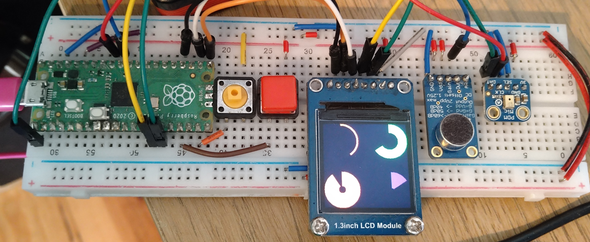
A slight “side track” to the flow of the project, but, Phil’s written a document about the “circular bar” graphic idea he had & some of the findings & thoughts as to how to make it better.
A slight “side track” to the flow of the project, but, Phil’s written a document about the “circular bar” graphic idea he had & some of the findings & thoughts as to how to make it better. Click here to download the PDF… This example requires some of the equipment featured above (OLEd screen) – but omits the mic / buttons for simplicity. The zip file of the code.py & libraries is here
Four “CircleBar” objects reacting to a generated angle value in CircuitPython
<EDIT> We’re super chuffed that we got featured in the Circuit Python newsletter </EDIT>