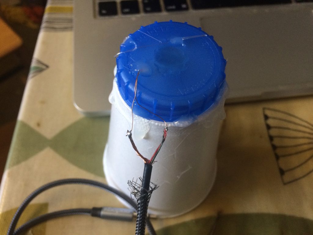
We are thinking that we could take the experiment into the realms of “playback / record” by adding a mic to the set up. There are several types of microphones to choose from, Martin started to use a 3 pinned MAX4466 mic, Phil used a 5 pinned Ada Fruit MAX9814 . Martin succinctly states:
“A microphone produces an analogue signal whereas the Pico needs a digital signal to work with. The RP2040 processor has four ‘analogue to digital’ converters, three of which are available on the Pico. An analogue to digital converter, ADC, converts the analogue signal to a digital signal that can be read by the Pico. The Pico ADC’s are 12 bit, returns a value between 0 and 4095. However CircuitPython is written to work across a number of devices and returns a 16 bit value, 0 – 65535”.
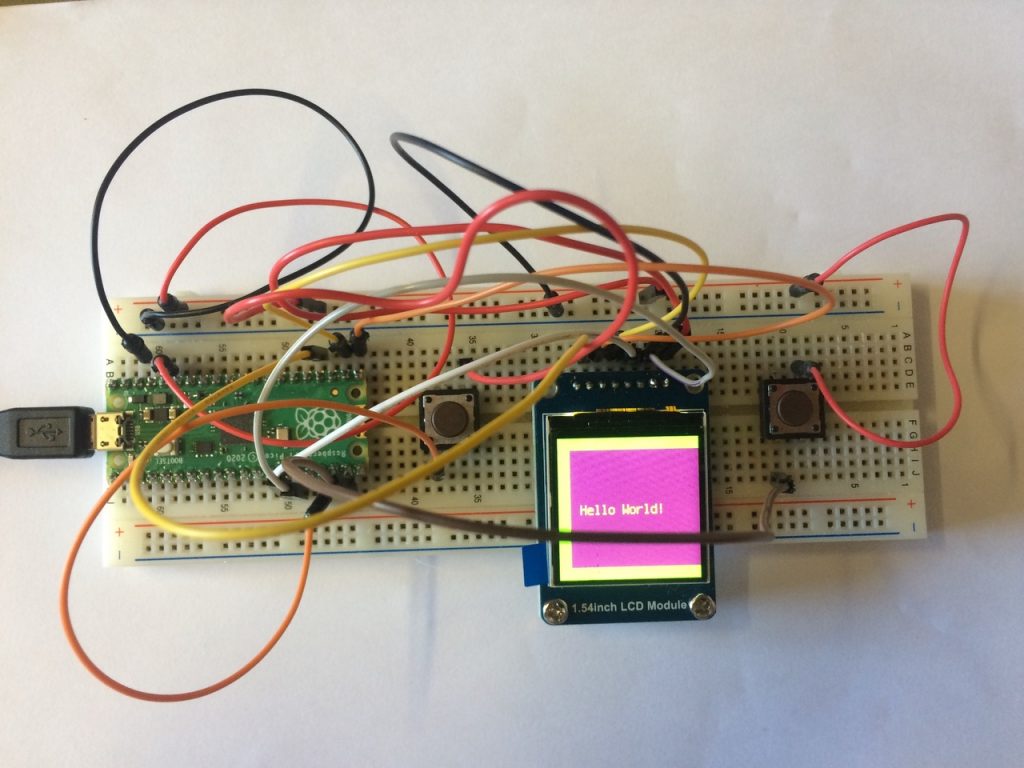
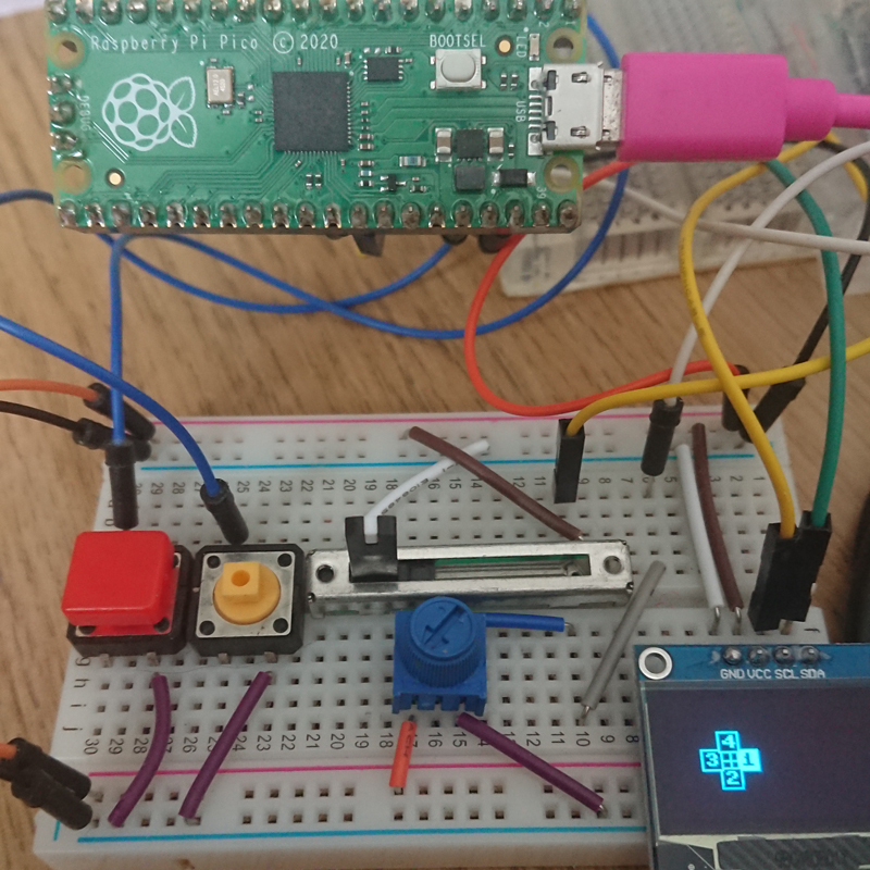
With these ranges in mind, Phil wrote the code to convert the mic signal into a range that displays a circle using vectorIO with a variable radius. Previously using circuitPython’s “displayIO shapes“, Phil found that it was difficult to change the size of a circle “on the fly” once a shape object had been created with displayIO. One of the great features of vectorIO is that “radius” is a mutable attribute (the value can be changed “on the fly”), so with a screen of 240 x 240 pixels, Phil placed the circle object in the centre of the screen & converted the mic input range to 0-120 px. After experimentation of what the actual values were for his MAX9814 Mic, Phil discovered that the “minimum” (at rest) was around 24,000 and the peak value was around 36000.
The code below is a very handy “mapping” function in python, we use it all the time in projects to convert a value from one range to the corresponding value in another range!
def mapFromTo(v, oldMin, oldMax, newMin, newMax):
   #v = passed value (should be inside the oldMin/oldMax range!)
   newV = (v-oldMin)/(oldMax-oldMin)*(newMax-newMin)+newMin
   return newV
Download Martin’s Week 3 pdf here
You can also download the zip of all the files needed for this week’s experiment here.