Audio amplifier: LM380

This is the first part of a new project, more details to be released later…

tr(uSDX)

Martin is a licensed radio amateur who enjoys building things. He was recently part of a UK group buy for a radio kit. The tr(uSDX) the radio is really tiny and can operate on five bands.

tr(uSDX) kit

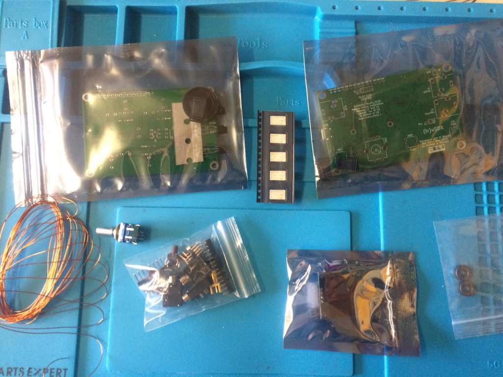
The main SMD parts were pre-soldered although Martin did have to solder on a couple of SMD parts, that had been sourced separately to the original PCB production. Other parts soldered on included all the connections and filter toroids. The whole build took a couple of hours. Once finished it was housed in a case the Phil had 3D printed.

3d Print3d housing

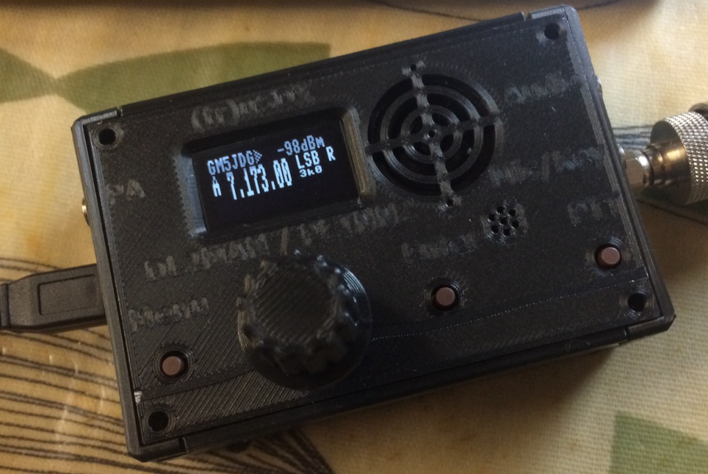
The radio works well and puts out around five watts. One annoying issue though is the speaker, it’s very small and the audio quality it produces is not very good. One solution is to connect either headphones or a powered speaker to the Audio out socket.

Amplifier

Martin purchased a small powered speaker from Amazon but it produced horrendous interference with the radio. He thought “why not build my own!” He’s part of a group aligned to the GQRP club who are building a scratch built radio transceiver, part of the build is an audio amplifier based on an LM380 chip.

Design

The design from the ‘scratch built’ group includes a pre-amp. Martin decided that he wouldn’t need this as the signal source was reasonably amplified already, and wondered if the LM380 was the right chip to use as it’s been around a long time. Researching the other solutions, including LM386, can be noisy and a little underpowered, TDA2003, used in many car audio systems and seems to offer similar performance to LM380.

Martin eventually decided to stick with the LM380 as he had built a circuit using it before and there were a number of similar designs found on the internet in use by other radio amateurs.

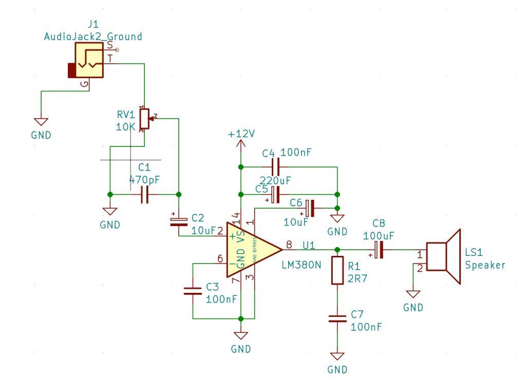
One design difference Martin made to the scratch built design was to use 100uF coupling capacitor to the speaker as this acts to roll off some of the audio frequency below 300Hz. The amplifier will primarily be used with speech in the range 300Hz – 3kHz. Additional capacitors were added to increase noise immunity from RF sources and reduce hum, particularly on the signal input. Supply voltage can be anything from 9-15V. I decided to use a 3” 8ohm speaker for output.

KiCad

Martin’s final design was drawn up in KiCad

Building

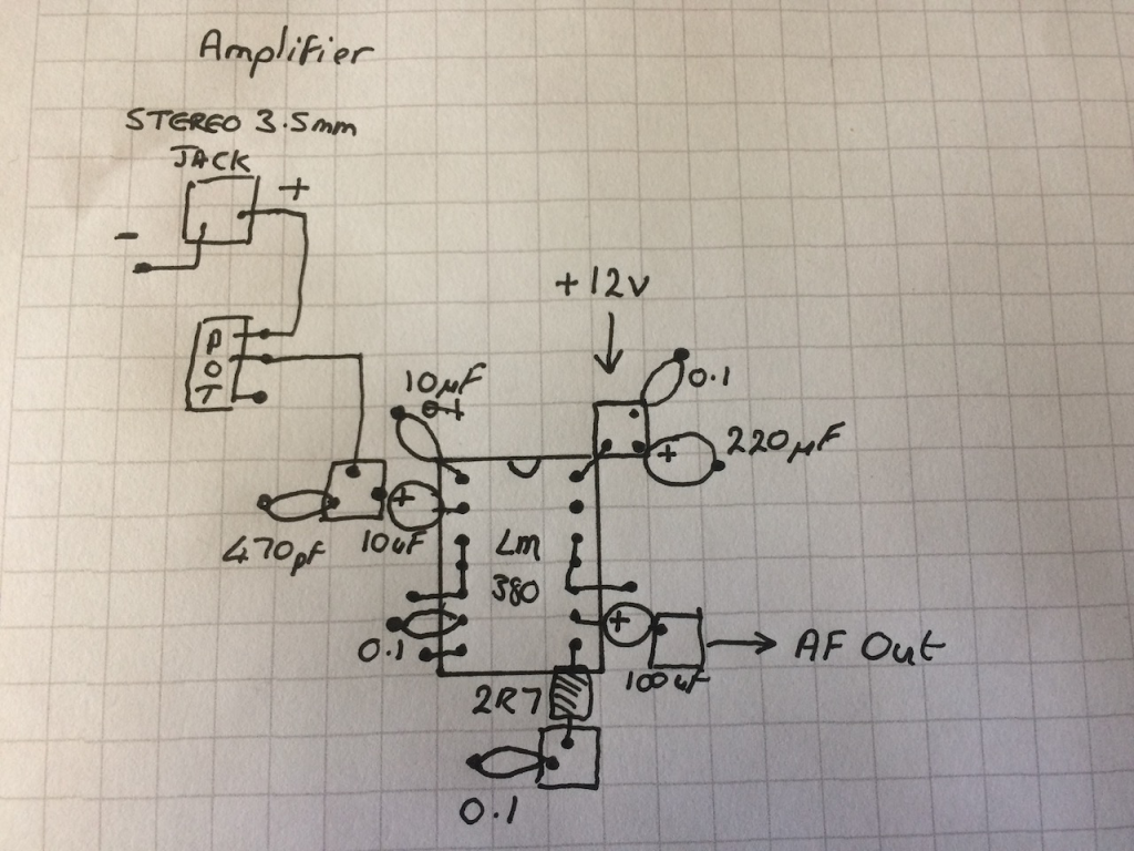
Using the Manhattan construction approach to building the design. Martin says he “finds it easiest to use prefabricated joining square called MeSquares for the build, these are also available from GQRP, for members, or a similar product is available from Kanga Products

The first step was to layout the design on 1/4” graph paper.

Initial circuit design on paper by Martin Evans

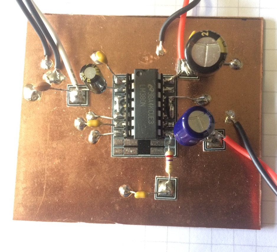
Then the parts were soldered to the single sided PCB. The squares were glued into place with super glue.

1st prototype

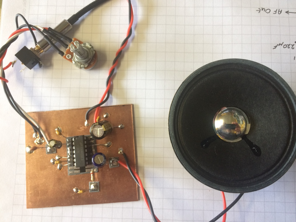
The final stage was to test it. Martin tested it using the output from the tr(uSDX) transceiver. The results were very favourable.

Video of the prototype in action

The LM380 runs a little hot so Martin will add some additional heat sinking to the pins 3,4,5 and 10,11,12 as detailed in the data sheet additionally the
sound could be improved by mounting the speaker into a small wooden box.

Week 9 : Adding a Real time clock to a Raspberry Pico

For our new project we think at some point we are going to need to have an accurate measure of time that has passed and for this we will need a real time clock.

For our new project we think at some point we are going to need to have an accurate measure of time that has passed and for this we will need a real time clock.

The Pico doesn’t have it’s own clock, and for that matter non of the Raspberry Pi family do, a quick google search revealed a few different boards that could offer this facility.

I decided to go with one that was based on a DS1307 and communicated via I2C. I ordered three of them from Amazon at a cost of £4.99. They arrived complete with installed batteries, with a claimed running time of a few years which would be more than enough for our project.

DS1307 Module

Another Google search was undertaken to find out how to connect them to a Raspberry Pi Pico. Most articles suggested that they were primarily a 5V device as they were originally designed for use with an Arduino and so would need to have two pull-up resistors moved from the board for use with the 3.3V system of the Pico. The resistors are R2 and R3 in the above image. The boards also needed to have headers installed.

Connections

Only four connections were needed:
GND: Ground
VCC: 3.3V
SDA: GP0
SCL: GP1

Luckily CircuitPython has a library for use with the DS1307, complete with an example code listing.

I installed the required libraries and ran the example code. An error came up complaining about a lack of pull-up resistors.

Martin’s RTC Set up with Resistors…

I installed a couple of resistors, anything around 3.3k should be fine, between the SDA/SCL pins and VCC (3.3V) and ran the code again.

This time there were no errors. The code, see below, has a part where you can set the time by changing the ‘if False’ statement to ‘if True’. Once this has been done change it back to False. The RTC clock will continue to keep the time even after the Pico has been powered off.

Code listing

import time
import board
import adafruit_ds1307


# To create I2C bus on specific pins
import busio
i2c = busio.I2C(board.GP1, board.GP0)    # Pi Pico RP2040

rtc = adafruit_ds1307.DS1307(i2c)

# Lookup table for names of days (nicer printing).
days = ("Sunday", "Monday", "Tuesday", "Wednesday", "Thursday", "Friday", "Saturday")

if False:  # change to True if you want to set the time!
    #                     year, mon, date, hour, min, sec, wday, yday, isdst
    t = time.struct_time((2022, 5, 6, 15, 2, 15, 5, -1, -1))
    # you must set year, mon, date, hour, min, sec and weekday
    # yearday is not supported, isdst can be set but we don't do anything with it at this time
    print("Setting time to:", t)  # uncomment for debugging
    rtc.datetime = t
    print()
# pylint: enable-msg=using-constant-test

# Main loop:
while True:
    t = rtc.datetime
    # print(t)     # uncomment for debugging
    print(
        "The date is {} {}/{}/{}".format(
            days[int(t.tm_wday)], t.tm_mday, t.tm_mon, t.tm_year
        )
    )
    print("The time is {}:{:02}:{:02}".format(t.tm_hour, t.tm_min, t.tm_sec))
    time.sleep(1)  # wait a second
Readouts from the RTC

Realisation

After doing this I realised that because I was connected to pin 36 (3V3 out) that I hadn’t actually needed to remove the on board resistors and wouldn’t need the added pull-up resistors either.

I soldered headers to the remaining two boards to test that I was correct and indeed I was. So we now have three working realtime clocks, but one of them needs pull-up resistors.

Week 8/9 : Oop Tree

Object Orientated Programming in CircuitPython to make Digital Trees

We think we’ve taken the Asteroids development as far as we can just now (looking at speeding up the FFT calculations)… but, in the mean time, Phil has started re-visiting an old passion… OOP Trees!

Object Orientated Programming in CircuitPython to make Digital Trees… Phil used to play with Macromedia Director 8 / 8.5 (!) and made some digital trees. Phil’s had an idea of re-visiting making OOP trees, but on the tiny Raspberry Pi Pico using CircuitPython…

Over 2 days, Phil’s successfully written a Tree Class, thinking of a tree as a series of “nodes” – He passed several key parameters to the Tree Class, an X,Y location, how many nodes the tree will have (“the Trunk”), how much those nodes can vary in direction from each other & how far they will be from each other. t = Tree() # Params cut out for ease here

Phil had a brainwave, to define all the lengths & angles “at the start” – and then “simply” multiply the values by a scale (from 0 to 1) – the “age” of the tree… so the entire tree is drawn but “scaled down” (to 0) at the start & in a loop, slowly increase the tree’s “age” by a tiny increment… giving the impression of growth! (it all worked smoothly! Not bad for a self taught N00B(!) – Phil’s sure there are probably a lot of pythonic conventions that need to be learned! ).

So, having a “working trunk” growing & stretching nicely, Phil wondered about adding branches… The thing is, they are nearly identical to a Trunk, just that the base of the 1st node isn’t “at a fixed point” (in the “ground”) – but a node on the Trunk (or even another Branch!). With a quick addition of “fNode” (“follow node”) – the Trunk having fNode = None & a branch having fNode = parentNode, he added in the code.py t.newBranch([2,3,3,4, 10]) The array passed, are positions of nodes in t (duplicates just add more branches to that node!). He even put in an error check to see if a node requested is in the range of the parent’s nodes! IT ALL WORKED! woohoo! The Branch grows just like the Trunk, but its base node follows the position of its parent node!

With the branches & trunk now growing nicely (and stopping growing when it reaches the scale of 1), Phil turned to add in leaves… a new Class “leaf” was added to the script & contains info of a colour of leaf, the radius of the leaf (using vectorIO.Circle objects) . Phil thought that the control of when / where & how many leaves appear should be decided by each node (on the trunk or branches). Passing several random numbers to determine how many, how big, how far away from the node they should be was passed in to the object. A few functions Phil’s made (“utility scripts”) like getting an X,Y position based on a known x,y position + length & angle (using Pythagoras) & adding a random range of R G B values to a “base R G B” colour to get variations of greens / browns (any colour!) – Phil rendered out leaves a hoy! But, things were slowing down again on the tiny Pico… So Phil decided to only render leaves when their parents reached specific criteria (age / length away from root) – and this gave a lovely effect of the leaves slowly blinking into existence, as the tree aged!

Phil was inspired & energised , getting into a “playful” development state…”I’ll try this!” he thought… boom! it works! And so, he added a few playful things, like a random “gust of wind” that jiggles the nodes occasionally, increasing & decreasing the scale quickly with the 2 buttons from week 1 … so many possibilities …

Anyway, if you want to have a play (& probably hone / improve the OOP!) download the scripts for the Pico set up here. Have fun!