

For our new project we think at some point we are going to need to have an accurate measure of time that has passed and for this we will need a real time clock.
The Pico doesn’t have it’s own clock, and for that matter non of the Raspberry Pi family do, a quick google search revealed a few different boards that could offer this facility.
I decided to go with one that was based on a DS1307 and communicated via I2C. I ordered three of them from Amazon at a cost of £4.99. They arrived complete with installed batteries, with a claimed running time of a few years which would be more than enough for our project.

Another Google search was undertaken to find out how to connect them to a Raspberry Pi Pico. Most articles suggested that they were primarily a 5V device as they were originally designed for use with an Arduino and so would need to have two pull-up resistors moved from the board for use with the 3.3V system of the Pico. The resistors are R2 and R3 in the above image. The boards also needed to have headers installed.
Connections
Only four connections were needed:
GND: Ground
VCC: 3.3V
SDA: GP0
SCL: GP1
Luckily CircuitPython has a library for use with the DS1307, complete with an example code listing.
I installed the required libraries and ran the example code. An error came up complaining about a lack of pull-up resistors.
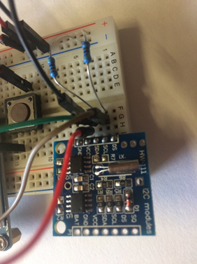
I installed a couple of resistors, anything around 3.3k should be fine, between the SDA/SCL pins and VCC (3.3V) and ran the code again.
This time there were no errors. The code, see below, has a part where you can set the time by changing the ‘if False’ statement to ‘if True’. Once this has been done change it back to False. The RTC clock will continue to keep the time even after the Pico has been powered off.
Code listing
import time
import board
import adafruit_ds1307


# To create I2C bus on specific pins
import busio
i2c = busio.I2C(board.GP1, board.GP0)    # Pi Pico RP2040

rtc = adafruit_ds1307.DS1307(i2c)

# Lookup table for names of days (nicer printing).
days = ("Sunday", "Monday", "Tuesday", "Wednesday", "Thursday", "Friday", "Saturday")

if False:  # change to True if you want to set the time!
    #                     year, mon, date, hour, min, sec, wday, yday, isdst
    t = time.struct_time((2022, 5, 6, 15, 2, 15, 5, -1, -1))
    # you must set year, mon, date, hour, min, sec and weekday
    # yearday is not supported, isdst can be set but we don't do anything with it at this time
    print("Setting time to:", t)  # uncomment for debugging
    rtc.datetime = t
    print()
# pylint: enable-msg=using-constant-test

# Main loop:
while True:
    t = rtc.datetime
    # print(t)     # uncomment for debugging
    print(
        "The date is {} {}/{}/{}".format(
            days[int(t.tm_wday)], t.tm_mday, t.tm_mon, t.tm_year
        )
    )
    print("The time is {}:{:02}:{:02}".format(t.tm_hour, t.tm_min, t.tm_sec))
    time.sleep(1)  # wait a second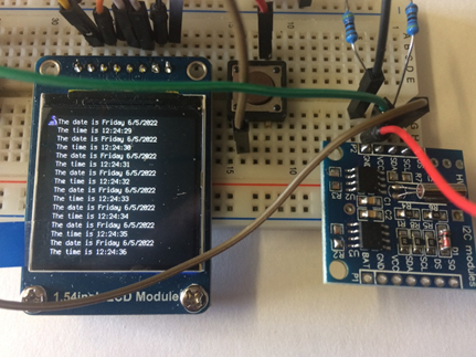
Realisation
After doing this I realised that because I was connected to pin 36 (3V3 out) that I hadn’t actually needed to remove the on board resistors and wouldn’t need the added pull-up resistors either.
I soldered headers to the remaining two boards to test that I was correct and indeed I was. So we now have three working realtime clocks, but one of them needs pull-up resistors.