Week Seven: OOP Asteroids and tone detection

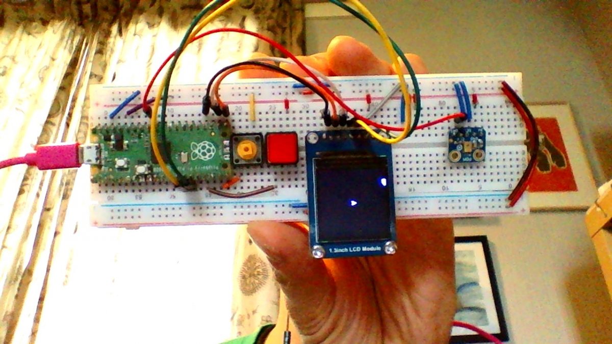
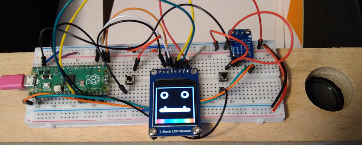
Working (but slow) Sound Controlled “Asteroids” with PDM mic on Raspberry Pi Pico by Digital Maker CIC

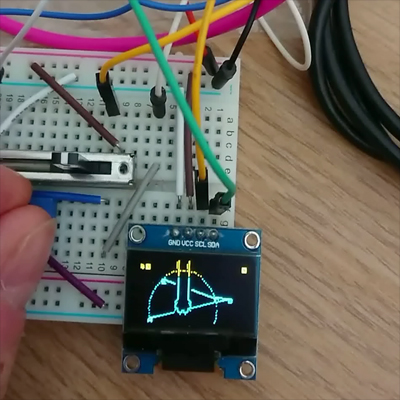
Using Martin’s Ada Fruit FFT experiment (week 5) and Phil’s OOP Asteroids, we started to get some sound controlling the Spaceship!

This week has proven to be quite a challenge.

We wanted to combine the knowledge gained previously from Phil’s Asteroids and Martin’s FFT code to make a game controlled by sound. Phil continued his work on the Asteroids and control of a small rocket capable of firing projectiles.
Martin looked at isolating individual tones, these could then be used for the control of the rocket. Three tones were needed for, boost, rotate and fire. He chose an online tone generator https://www.szynalski.com/tone-generator/ to generate the three required tones.

A tutorial https://learn.adafruit.com/light-up-reactive-ukulele/software found online was particularly helpful. This led to the following CircuitPython code:

"""FFT Tone detection
to work with ulab on Raspberry Pi Pico"""

from time import sleep
import audiobusio
import board

from ulab import numpy as np
from ulab.scipy.signal import spectrogram
import array

#---| User Configuration |---------------------------
SAMPLERATE = 16000
SAMPS = 256

fft_size = 256

# ============== make the PDM mic object =============== #

mic = audiobusio.PDMIn(board.GP27_A1, board.GP0,
                                sample_rate=SAMPLERATE, bit_depth=16, startup_delay=0.05, mono=True)

#use some extra sample to account for the mic startup
samples_bit = array.array('H', [0] * (fft_size+3))

# Main Loop
def main():
    max_all = 10
    while True:
        mic.record(samples_bit, len(samples_bit))
        samples = np.array(samples_bit[3:])
        spectrogram1 = spectrogram(samples)
        # spectrum() is always nonnegative, but add a tiny value
        # to change any zeros to nonzero numbers
        spectrogram1 = np.log(spectrogram1 + 1e-7)
        spectrogram1 = spectrogram1[1:(fft_size//2)-1]
        peak_idx = np.argmax(spectrogram1)
        peak_freq = peak_idx * 16000 / 256 / 2
        #print((peak_idx, peak_freq, spectrogram1[peak_idx]))
        
        if peak_freq > 1000 and peak_freq < 1150:
            print("Fire")
        elif peak_freq > 500 and peak_freq < 550:
            print("Rotate")
        elif peak_freq > 225 and peak_freq < 275:
            print("boost")
        else:
            print(peak_freq)
        sleep(0.1)

main()

The code worked reasonably well so the next task was to incorporate it into Phil’s asteroid code.

This proved quite challenging as once the two were combined together. The frequency returned by the microphone was always 0.0.

Various methods were tried, adding the Mic as object, calling it as a function and directly adding it to the main code.py. Adding it to directly to code.py was the final stage but still wasn’t providing the desired results.

Next we resorted to commenting out elements of code, the final conclusion was that some of the print statements were causing timing errors that caused the spectrogram to return values of 0.0. We aren’t quite sure why but once these were reduced to a minimum the code started working.

The final code with libraries is available as a zip file here.

It’s quite slow – the FFT calculations might be pushing the Pico to the edge of its computing power! Phil is exploring how to hone the OOP too, to see if he can eek out a few more milliseconds

Week 6: OOP asteroids

With the use of the FFT code to recognise sounds / frequencies, we had an idea that a game could be controlled with specific sounds

With the use of the FFT code to recognise sounds / frequencies, we had an idea that a game could be controlled with specific sounds… Phil started to look at OOP again (Object Orientate Programming) & wanted to create a game of “Asteroids” but instead of pressing a button to “shoot” , making a laser “pew pew” sound would activate the shooting … Ambitious? has it been done before?

Phil loves a bit of OOP, and recently bought the fantastic book by Dusty Phillips and with the previous lessons in creating vectorIO polygons, he started out making a large polygon with randomly spread out “nodes” (thinking about large “initial” asteroids and how they would break down & split into smaller objects, with their own properties of speed, direction (vectors), edges etc).Phil’s 1st attempt at creating Asteroids

There are a few bugs, mostly from edge detection / re-draw – but it’s looking promising!

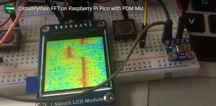
Week 5: FFT Waterfall

Martin has been following the #AdaFruit example of FFT

Martin has been following the #AdaFruit example of FFT ( fast Fourier transform) to convert the microphone input into a visual representation (spectrum) with great results! The code for this can be downloaded here

Week 3/4 – CircularBar object with vectorIO

A slight “side track” to the flow of the project, but, Phil’s written a document about the “circular bar” graphic idea he had & some of the findings & thoughts as to how to make it better.

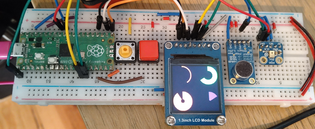
A slight “side track” to the flow of the project, but, Phil’s written a document about the “circular bar” graphic idea he had & some of the findings & thoughts as to how to make it better. Click here to download the PDF… This example requires some of the equipment featured above (OLEd screen) – but omits the mic / buttons for simplicity. The zip file of the code.py & libraries is here

Four “CircleBar” objects reacting to a generated angle value in CircuitPython

<EDIT> We’re super chuffed that we got featured in the Circuit Python newsletter </EDIT>

Week 3 : Adding a microphone

We are thinking that we could take the experiment into the realms of “playback / record” by adding a mic to the set up.

We are thinking that we could take the experiment into the realms of “playback / record” by adding a mic to the set up. There are several types of microphones to choose from, Martin started to use a 3 pinned MAX4466 mic, Phil used a 5 pinned Ada Fruit MAX9814 . Martin succinctly states:

“A microphone produces an analogue signal whereas the Pico needs a digital signal to work with. The RP2040 processor has four ‘analogue to digital’ converters, three of which are available on the Pico. An analogue to digital converter, ADC, converts the analogue signal to a digital signal that can be read by the Pico. The Pico ADC’s are 12 bit, returns a value between 0 and 4095. However CircuitPython is written to work across a number of devices and returns a 16 bit value, 0 – 65535”.

With these ranges in mind, Phil wrote the code to convert the mic signal into a range that displays a circle using vectorIO with a variable radius. Previously using circuitPython’s “displayIO shapes“, Phil found that it was difficult to change the size of a circle “on the fly” once a shape object had been created with displayIO. One of the great features of vectorIO is that “radius” is a mutable attribute (the value can be changed “on the fly”), so with a screen of 240 x 240 pixels, Phil placed the circle object in the centre of the screen & converted the mic input range to 0-120 px. After experimentation of what the actual values were for his MAX9814 Mic, Phil discovered that the “minimum” (at rest) was around 24,000 and the peak value was around 36000.

The code below is a very handy “mapping” function in python, we use it all the time in projects to convert a value from one range to the corresponding value in another range!

def mapFromTo(v, oldMin, oldMax, newMin, newMax):
   #v = passed value (should be inside the oldMin/oldMax range!)
   newV = (v-oldMin)/(oldMax-oldMin)*(newMax-newMin)+newMin
   return newV

Download Martin’s Week 3 pdf here

You can also download the zip of all the files needed for this week’s experiment here.

Week 2 – making & adding a speaker!

We love a bit of sound! So, we’ve decided to add a speaker to the Pico set up…

We love a bit of sound! So, we’ve decided to add a speaker to the Pico set up… But with the added fun of trying to make one from scratch!Martin’s DIY Speaker

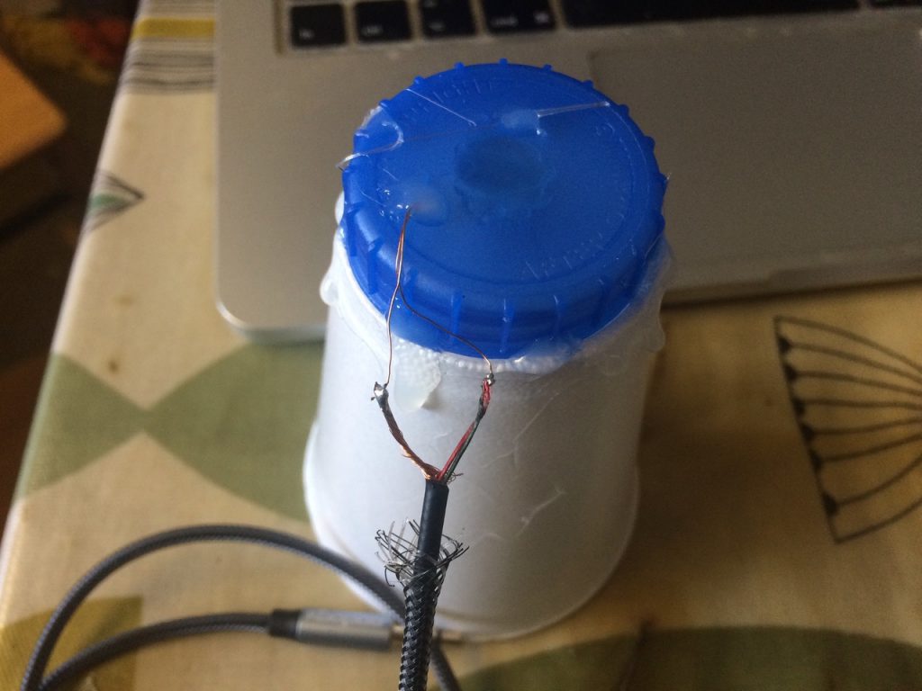
Martin used some re-cycled motors for the insulated copper wire for the guts of a DIY Speaker & has had success! (all be it quiet, but, this project is about testing, trying, proof of concept etc)…

DIY Speaker!

For the full documentation, & Step By Step Guide on how to make a speaker from a cup & some old motor / electronic parts, download “week 2” pdf sheets, with code & materials lists etc.Phil’s Set up uses a bought speaker & Ada Fruit Amplifier

Week 1 : Pico & OLEd + 2 buttons…

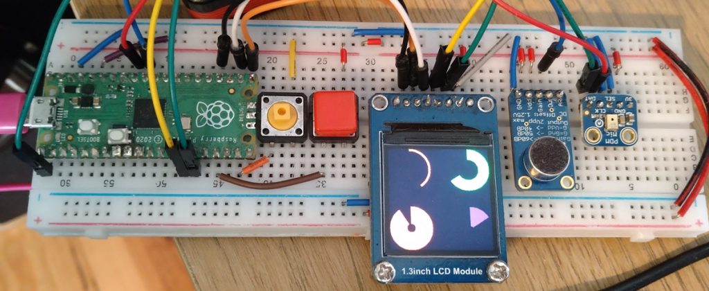
We started with a #raspberryPi #Pico & 240 x 240px OLED.

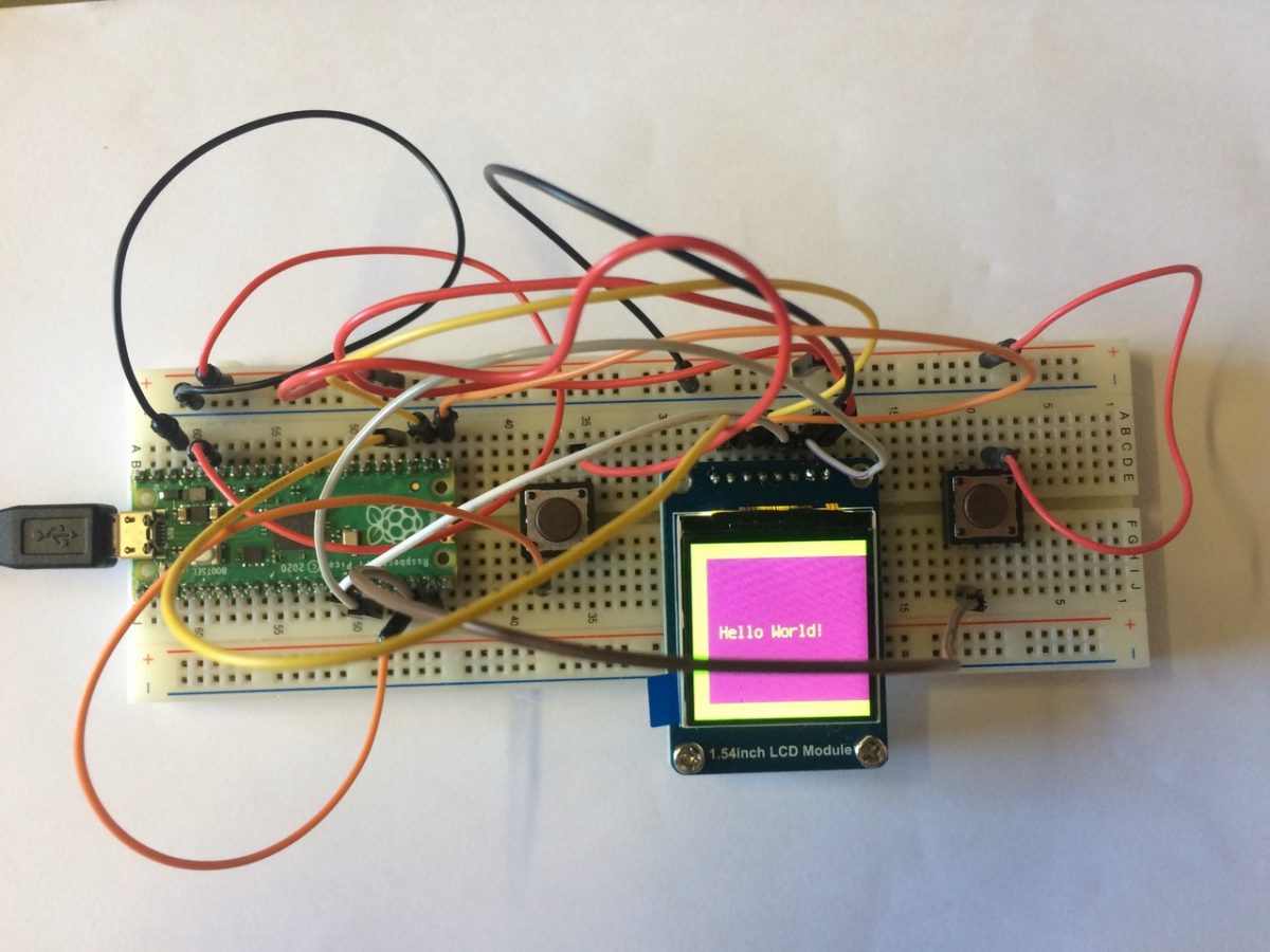
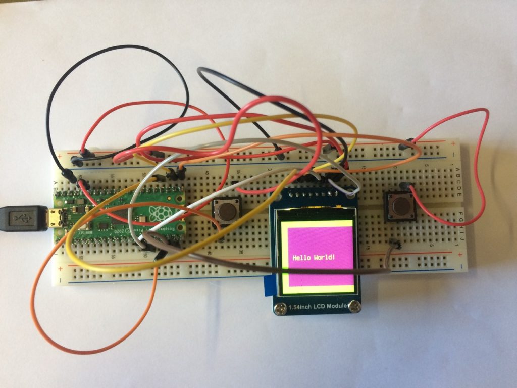
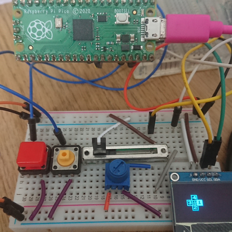
We started with a #raspberryPi #Pico & 240 x 240px OLED. Having worked with these as a base for the DinkyOSC we thought it would be a good place to start. We’ve added 2 buttons to the set up & control BMPs with adafruit_imageload & displayio . Below is a photo of the initial setup & we’ve included a PDF of the set up etc. here.

Raspberry Pi Pico + OLED screen / electronics buttons on prototyping breadboard.
Raspberry pi Pico + OLEd + Buttons + Breadboard

Dinky OSC “Paw Game”

Phil is experimenting & learning how to control text / images on the #SSD1306 (128×64 px OLED display) attached to the #RaspberryPi #Pico – he’s ended up making a little game that involved moving a “Cat Paw” around with a slider & potentiometer and a button press “grabs” at what’s underneath the paw.

Phil is experimenting & learning how to control text / images on the #SSD1306 (128×64 px OLED display) attached to the #RaspberryPi #Pico – he’s ended up making a little game that involved moving a “Cat Paw” around with a slider & potentiometer and a button press “grabs” at what’s underneath the paw.

the code for the game is here

There are 8 “targets” to grab (you can change that by changing the line:
dots = 8 ) & the targets fly around with a random vector, each connecting to the next target with a line. The paw has a “hot spot” (the middle of the paw) and a “circle object” draws around it using the distance from it to the 1st target in the list (calculated by some simple trig in the utilities.py module, after an angle & radius has been calculated from the two objects’ positions)

Phil’s commented the main.py script as best he can, but, if you need any explanation, just holler!

Dinky OSC “image objects” drawn on SSD1306 128×64 px OLED screen controlled by GPIO pot, slider, buttons.

OOP Orbits

Phil has been learning OOP (Object Orientated Programming) in Python & applying it to his #dinkyOSC development on the raspberry pi pico. We’re aiming for two styles of GUI, a “simple” numbers / settings interface (like digital representation of a “normal” midi device, and a “visually creative” interface (what ever that develops into!)

Phil has developed an OOP system to create & manage “orbiting objects”

This “Orbit OOP” script creates an object that keeps track of a centre point, and equally spaces points around it using some simple trigonometry based on the slider & rotary Potentiometer’s values. (Slider = Length of radius to orbit, pot = angle (0-259° (converted to Radians (Degree * (Pi / 180.0)))

Button 1 & 2 “add & subtract” points (with a minimum of 1 & maximum of 9 points). When a point is added, the “orbit object” calculates the angular segments (4 objects = 90° segments, 5 object = 72° etc) and re-draws the objects accordingly. Phil also created different “image objects” that can follow the orbit points, but stuck with a simple BOX object (text box with padding) that follows the orbit point from its own centre (x,y for an object is usually top, left, so he subtracted 1/2 the width & height from the x,y orbit).

These scripts are still considered “experiments” but Phil had been asked by a few people online (when posting videos) if the code was available… so, here it is in a zip for you to play with. Remember, Phil’s still learning, so if it doesn’t “look like professional python code” do let him know where he can improve!